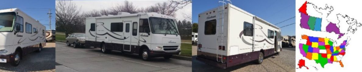
 Prior to purchasing our “New-to-Us” 2001 Mirada, we took it on a short test drive. One of the items on the list was to evaluate the handling. During the test drive the handling seemed tight and responsive, and didn’t appear to have any nasty behaviors.
Back at the dealer, I crawled around underneath, I didn’t know specifically what I was looking at, but generally, all the bushings and movable parts looked ok and I didn’t see anything lose.
On our inaugural 6000 mile trip across southern United States, I had a lot of time behind the wheel. I discovered that during crosswinds or when passing or being passed by large vehicles, I had to keep both hands on the wheel and continue to work at it as the Mirada wondered and needed constant correction. It wasn’t beating me to death, but it certainly wasn’t driving easy like a new car. I had to constantly “drive” it.
![]() If you subscribe to the irv2 web site forums, then you may be familiar with a very popular topic for F53 owners, Cheap Handling Fix, or commonly referred to as “CHF”. This thread specifically addressed this handling issue and offered a simple remedy that cost nothing but a little time to implement.
If you subscribe to the irv2 web site forums, then you may be familiar with a very popular topic for F53 owners, Cheap Handling Fix, or commonly referred to as “CHF”. This thread specifically addressed this handling issue and offered a simple remedy that cost nothing but a little time to implement.
 On the F53 chassis, there are torsion bars on both front and rear axles. Each torsion bar has two sets of attachment mounting holes for the link attachment. Ford put these two holes on the torsion bar to allow the end user to adjust the stiffness and subsequent side to side sway. The factory supplied adjustment is loose and offers very little sway control. The other adjustment hole provides stiffer torsion bar and a lot of sway control.
The CHF simply moves the link rod attachment from the forward mount hole on the torsion bar to the to the rear mount hole on the torsion bar. (see photos at bottom of article)
By moving the link rod, it now twists the torsion bar more for a given movement on one side. This twisting, or torsion, is transferred to the other side of the axle and tries to keep the axle straight, in line with the frame.
This makes the axle to frame a little stiffer, i.e. the Mirada doesn’t respond to those sudden gusts of wind that tend to push on the side of the MH.
I read through the majority of the posts on the CHF thread, all who performed the CHF reported marked improvement. There were also other recommendations to improve the suspension, but I decided to handle the CHF first.
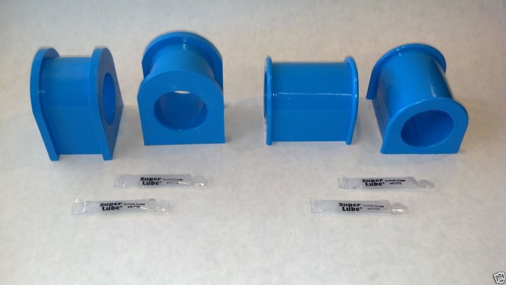
As part of the CHF modifications, I decided to replace the torsion bar bushing (see above). These are available on e-bay for about $80 for both the front and rear bushings.
NOTES – When doing the front CHF, some people just moved the link rods to the other hole in the torsion bar. I elected to follow the suggestions of others and make the link rods longer to get a little better geometry. See the drawings at the end of this article.
If you just move the link rods, you cannot re-use the lower “Z” brackets (if you have them). If you make your link rods longer, you can re-use them if you use a 12 inch pipe. If you screw up like I did and make the pipe 10 inches, you cannot re-use the “Z” brackets as the link rods will hit them. (I modified my “Z” brackets and used them. There is ongoing discussion as to what the “Z” brackets usefulness really is.
You may or may not have “Z” brackets.
I used an impact driver to get the bolts off, but they should come off with standard socket sets and wrenches.
STEP BY STEP
Front CHF
1) I removed both front link rods (15mm and 18mm). The bolts that go thru the tension bar can’t be removed until both sides are removed, they hit the leaf spring.
Remove the bolts for the lower “Z” brackets. You may need to loosen the upper “Z” bracket bolts a little bit to get the link rod out from the upper attach point.
2) I pressed the bushings out of the link rods, they looked OK so I’ll reused them.
Squirt a little oil on the bushings, make sure you can turn them by hand before you try and press them out. If you can turn them easily by hand, they should press out without any damage.
3) Use a die grinder and cut the rods in half.
4) I then cut two pieces of 1/2 inch gas pipe 10 inches long.
IMPORTANT – If I were doing this again, I would make the pipe 12 inches long, this will give a little better clearance to the “Z” brackets
5) Slide the two halves of the link rods into the pipe and weld the pipe to the link rods. Clean and paint
6) Reinsert the bushings. I use a little dish soap to lubricate the bushing and pressed them back in.
7) On the front torsion bar, I removed the bolts and pulled the torsion bar off.
8) My bushings were in good shape, but I installed the new bushings anyway.
9) Spread a little lubricant on the torsion bar and insert the new bushings.
10) Reinstall the torsion rod and start the bolts, but don’t tighten yet.
11) Install the link rods on the top first, don’t tighten yet.
12) Install the bottoms of the link rods in the hole closest to the axle, don’t tighten yet.
If you made your link rods with 10 inch extensions, you will not have room to re-use the “Z” brackets. If you made them 12 inches, then you should have clearance, so re-use the “Z” brackets.
13) Tighten the tops of the link rods.
14) Tighten the bottom of the link rods
15) Tighten the torsion bolts
Your finished with the front, now move to the rear.
Rear CHF
*** IMPORTANT – You need to protect the ABS sensor on the top of the differential. Maybe take a small piece of lumber and tape it to the top of the differential so the bar cannot hit the sensor.
If the rear torsion bar is moved , it could hit the sensor and break it. I speak from experience. They are $17 each, and can be a real %^@#^#$$#^ to get out if they break off.
The rear link rods don’t need to be removed, their length is OK. so you only need to remove the bolts on the bottom. If you have a “Z” bracket, the bolt that goes through the link rod is (maybe) part of the “Z” bracket.
1) Install something to protect the ABS sensor. A small piece of wood!
2) Remove the bolts from the bottom of the link rods, both sides.
3) If your replacing the rear bushings, remove the bolts from the bushing plates. The bolts are 19mm, the nut plates should be welded to the axle.
4) Use EXTREME caution, when removing the torsion bar, this is where you’ll hit the ABS sensor. watch the top of the torsion bar where it crosses over the differential. It passes within an inch of the ABS sensor. (crunch sound is not good)
5) Cut the old bushings off, put a little lube on the torsion bar, install the new bushings on the torsion bar.
I used a small hammer to tap the bushing plates back onto the bushings .
6) Carefully lift the torsion bar back in place and start all four bushing plate bolts. Don’t tighten them yet.
7) If you have “Z” brackets, flip them around so the long bolts go into the rear holes on the torsion bar.
8) Connect the link rods on both sides to the rear torsion rod hole, start all the bolts and nuts before tightening anything.
9) Tighten the torsion rod bushing plate bolts.
10) Tighten the link rods.
11) If you installed something to protect the ABS sensor, remove it and look carefully at the sensor to make sure its not damaged.
THATS IT – Go for a test drive. 🙂
Installation photos and drawings
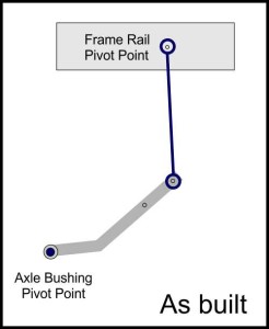
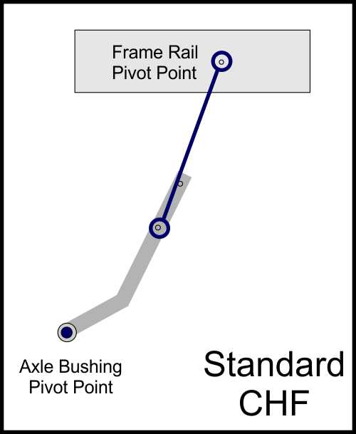
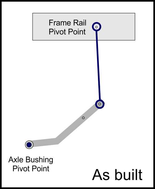 This is a drawing of the front torsion bar and link rods. This is what it looks like before you do the CHF.
 If you do not make the link rods longer, this is what it will look like after the CHF.
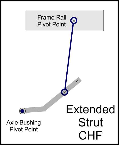 If you make the link rods longer, it will look like this.
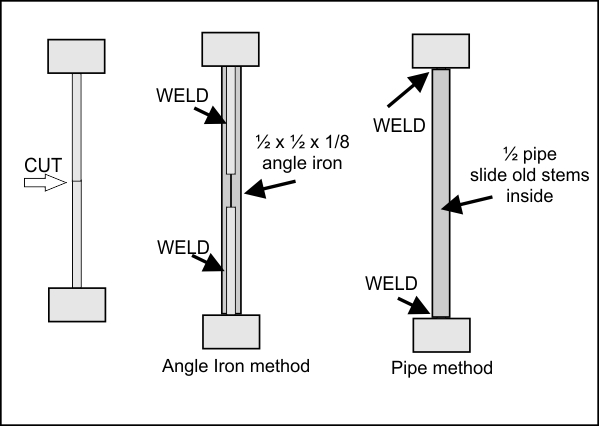 Remove the bushings, then cut the link rod in half. Cut a 1/2 inch pipe 12 inches long, slide the link rods into it and weld them up. (don’t use angle iron, use 1/2 pipe)
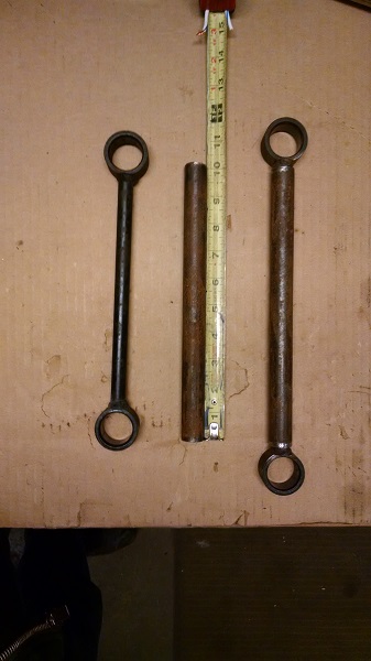 These are mine, I made them 10 inches. If i were doing it again, I would make them 12 inches.
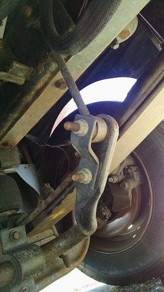 This is the front before CHF, Notice the “Z” bracket. You may not have this.
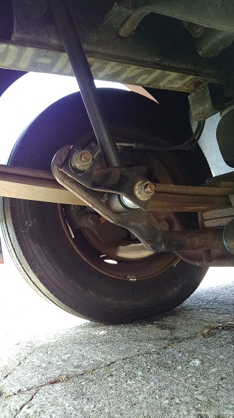 The longer link rod is installed on the rear hole. I had to severely modify my “Z” brackets. If I had made the link rods with a 12 inch pipe, I wouldn’t have had top do this.
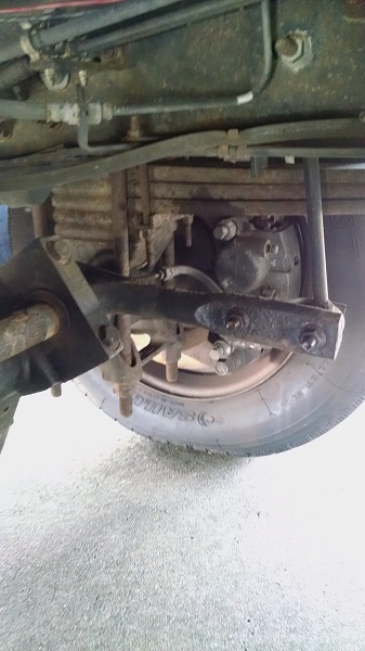 This is the rear torsion bar, notice the link rod is connected to the front hole on the bar.
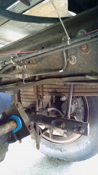 The rear link rod is mounted in the rear hole. The “Z” bracket was flipped over. Notice the new torsion bar bushings.
The “links” are not “tie rods” as the term is commonly used in automotive terms. You are dealing with front and rear “anti roll bars”. The process of using the holes closer to the bar mount on the axle makes the bar stiffer (harder) to bend, stiffing the roll rate. The coach will feel more stable. The
“links” take a lot of stress and need to be well made. The greater the diameter the bar—-the stiffer; the closer the “link” to the bar—–the stiffer it will be.
Yup, Everything Wayne said. 🙂
My qx is why doesn’t FR fix these handling problems before they sell these rigs? My FR3 was hazardous before I installed a Blue Ox Tru Trac to connect the differential to the frame. Shame on Forest River.
Can I just buy a longer rod instead of making one?
Greg, I don’t think so. I’ve seen this question asked on other forums, but there is never an answer.
If you know someone who can weld, its easy to make them longer. Just don’t weld on the links with the bushings installed, you’ll melt them.
Color me stupid but I still can’t figure out where I can get a non adjustable link. I have read most of the CHF posts and its like reading War and Peace.
As I lay under my MH I see I need links 12″s + -. I do not want to manufacture my own and don’t have the welding experience. Do you have a OEM part number?
Thanks
Scott
I don’t know of any aftermarket links.
If you have a local machine shop, maybe print out the little drawing that shows how to do it with the 1/2 inch water pipe.
I would make the water pipe 13 inches long.
They (you) need to remove the rubber bushings from the links before welding the pipes, otherwise you’ll melt the rubber bushings.